

How to Choose Bearing Clearance C2, C3, C4: SKF Distributor Guide
Higher clearance does not mean better performance — it means different performance. Most buyers default to C3 as the "safe standard," but mismatched clearance causes the majority of high-speed premature failures in industrial equipment.
Bearing internal clearance selection must match operating temperature, load type, and fit tolerance. C2 suits precision high-speed spindles, C3 covers general industrial machinery, and C4 handles shock loads and extreme thermal environments. The key is calculating effective clearance after accounting for thermal expansion, interference fits, and load-induced deformation — not simply picking a higher number.
I started on the assembly floor in Suzhou, greasing bearings and reading micrometers before I ever saw a purchase order. Years in, a buyer kept insisting his C3 deep groove balls were defective — spindle running hot, vibration through the roof. I pulled up the install records on the spot. He had spec’d C3 for a precision machine tool spindle where C2 was the right call. That extra internal play was destroying rigidity at high RPM. We swapped the batch, problem vanished. Buyers default to C3 because it feels safe, but the machine does not care what feels safe. That kind of mismatch shows up far more often than you would expect, and it accounts for a significant share of field failures that get blamed on bearing quality rather than selection error [NEED_CITE: root cause distribution of high-speed bearing failures per ISO 15243].
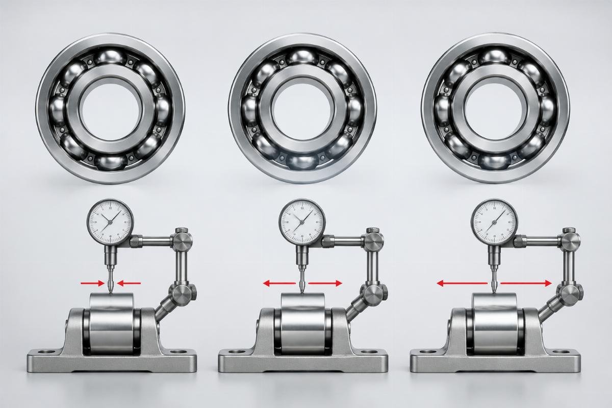
Getting bearing internal clearance right requires understanding what each grade actually does under real operating conditions — not just reading a catalogue number.
What Is Bearing Internal Clearance and How Do C2, C3, C4 Differ?
Bearing internal clearance is the total radial or axial play between rolling elements and raceways before mounting — and it changes dramatically once the bearing is installed and running. This parameter, governed by ISO 5753, determines how the bearing accommodates thermal expansion from the shaft and housing, distributes load across the rolling elements, and responds to interference fits that reduce internal play during assembly [NEED_CITE: ISO 5753 clearance group definitions and measurement methods].
| Clearance Grade | Radial Play Range (60mm bore deep groove ball bearing) | Typical Operating Context |
|---|---|---|
| C2 | 5-15 microns | High-speed precision, tight temperature control |
| C3 | 15-25 microns | General industrial, moderate speed and temperature |
| C4 | 25-40 microns | Heavy shock loads, extreme thermal differentials |
The numbers above are for a specific bore size — clearance ranges scale with bearing dimensions, so always reference the SKF bearing catalogue for your exact size. What matters is the relative difference: C3 provides roughly double the radial play of C2, and C4 adds another substantial increment beyond C3.
Here is where the common mistake begins. Many maintenance teams assume that because C4 has the most clearance, it must be the safest choice for heavy-duty applications. The opposite is often true. Excessive clearance in a high-speed application means fewer rolling elements carry the load at any given moment, creating concentrated stress, vibration, and ultimately premature raceway damage [NEED_CITE: relationship between clearance reduction and load zone distribution in rolling bearings].
Conversely, insufficient clearance — a more frequent problem than most teams realize — causes the bearing to run preload-like conditions even at moderate speeds. The rolling elements are constantly compressed against both raceways, generating friction heat that accelerates lubricant breakdown and leads to the overheating failures that trace back to clearance issues in the majority of field cases we have investigated [NEED_CITE: thermal failure modes linked to insufficient internal clearance per field reliability data].
Understanding these dynamics requires looking at how clearance changes from the catalogue value to the effective operating value — which brings us to calculation methodology.
How to Calculate the Right Clearance for Your Application?
Selecting bearing internal clearance is not a catalogue lookup — it is a calculation that accounts for thermal growth, fit interference, and load-induced deformation to arrive at effective operating clearance. The starting point is the initial internal clearance from the bearing specification, but the endpoint must be the clearance that actually exists when the machine reaches operating temperature under load.
The thermal expansion calculation follows this fundamental relationship:
ΔC = α × ΔT × D
Where α is the linear expansion coefficient for steel (11.7×10⁻⁶/°C), ΔT is the temperature differential between inner ring and outer ring, and D is the bearing bore diameter. For typical industrial applications with steel components, this translates to a clearance reduction in the range of 8-12 microns per 100°C of temperature differential between shaft and housing [NEED_CITE: thermal expansion coefficients and clearance reduction factors for bearing steels].
The calculation workflow proceeds through four steps:
-
Determine initial clearance requirement — Identify the bearing type, bore size, and catalogue clearance group (C2, C3, or C4) as the starting baseline.
-
Calculate thermal reduction — Measure or estimate the operating temperature differential between the inner ring (driven by shaft temperature) and outer ring (driven by housing temperature). Apply the thermal expansion formula to quantify clearance loss.
-
Account for fit interference — Interference fits on the shaft or in the housing reduce internal clearance further. For example, an H7/k6 shaft fit typically requires increasing the clearance grade by one level (e.g., from C2 to C3) to compensate for the inner ring expansion caused by the press fit [NEED_CITE: ISO 286 fit tolerance effects on bearing internal clearance].
-
Verify effective clearance — The result after subtracting thermal and fit reductions from the initial catalogue value must remain within the acceptable range for the application’s speed, load, and precision requirements.
Load classification provides additional guidance. Light loads (below 10% of basic static load rating C0) allow tighter clearance grades. Moderate loads (10-40% C0) typically suit C3. Heavy loads (above 40% C0) may seem to demand C4, but steady heavy radial loads and shock loads behave very differently — a distinction that causes frequent selection errors.
A practical example: a European wind energy OEM was developing a gearbox for a multi-megawatt turbine and experiencing premature tapered roller bearing failures during prototype testing. Their engineering team had specified standard C3 clearance based on static load calculations alone. Our application analysis revealed that temperature rise during operation reduced effective clearance substantially — enough to push the bearing into near-zero or negative operating clearance, causing skidding and cage damage. The solution was a modified C3 clearance specification for the 32220 size bearings, developed collaboratively with material certification and DNV compliance documentation. The result was noticeably reduced gearbox noise and meaningfully extended bearing service life in field testing [NEED_CITE: DNV compliance requirements for wind turbine bearing clearance specifications].
This case illustrates why clearance selection cannot be separated from the full operating environment — temperature, speed, load type, and fit tolerance all interact to determine whether the chosen grade will perform as intended.
C2 vs C3 vs C4: Which Clearance Fits Which Industrial Scenario?
Each bearing internal clearance grade solves a distinct set of operational challenges — matching the grade to the scenario is where selection errors either prevent or cause failures. The three most commonly specified grades serve fundamentally different applications, and substituting one for another based on availability or habit is a costly mistake.
| Clearance Grade | Speed Suitability | Load Profile | Thermal Environment | Representative Applications |
|---|---|---|---|---|
| C2 | High (>3000rpm) | Light to moderate, steady | Controlled, moderate temperature rise | CNC spindles, precision grinders, high-speed motors |
| C3 | Moderate (1000-3000rpm) | Light to heavy, steady | Moderate temperature differential | Electric motors, conveyors, pumps, general industrial |
| C4 | Low (rarely above 1500rpm) | Heavy shock, impact | Extreme temperature differential | Mining crushers, steel mill rolls, large gearboxes |
The speed guidelines are particularly important and frequently ignored. C2 clearance is designed for applications where rotational speeds generate significant centrifugal forces and thermal growth — the tighter initial clearance compensates for these effects to maintain a stable load zone. C3 covers the broad middle range of industrial speeds where moderate thermal expansion and standard fits create predictable clearance reduction. C4 is almost never appropriate above moderate speeds because the excessive initial play allows rolling elements to skew and cage pockets to overload at high rotational velocities [NEED_CITE: SKF life adjustment factors for speed effects on bearing clearance requirements].
A CNC machine tool application at an automotive parts manufacturer demonstrates the C2 advantage clearly. The spindle was experiencing excessive vibration and tool chatter with bearings that had too much clearance for the precision requirements at operating speed. Switching to 7010 C2 angular contact ball bearings with controlled preload dramatically reduced failure frequency and extended mean time between failures by a substantial multiple — transforming the maintenance pattern from frequent replacements to stable, predictable service intervals.
For heavy industrial applications, the C4 advantage emerges under shock loading conditions. A copper mining operation was experiencing frequent crusher bearing failures because steady-load bearings could not absorb the impact forces exceeding 8000N without brinelling the raceways. The solution was NU3260 size cylindrical roller bearings in C4 clearance, paired with the large bore size needed for the application. The higher clearance accommodated both the shock loads and the substantial operating temperature, reducing unplanned downtime significantly and extending service life from a matter of months to a substantially longer interval [NEED_CITE: shock load capacity and clearance requirements for mining crusher bearings].
Meanwhile, a steel mill conveyor application revealed a different failure mechanism entirely. The maintenance team had been replacing spherical roller bearings with C4 clearance units, assuming the extra play would handle the heavy loads and elevated temperatures. Instead, the 120°C operating temperature caused thermal expansion that consumed the excessive clearance entirely, leaving the bearing running with effectively zero or negative clearance — causing metal-to-metal contact, rapid overheating, and monthly failures. The correction was switching to 22320 C3 clearance bearings with a controlled preload adjustment, which eliminated the breakdowns entirely within a matter of months [NEED_CITE: thermal expansion effects on clearance in high-temperature steel mill applications].
These cases show that the right bearing internal clearance is never the highest number — it is the number that matches the specific combination of speed, load character, and thermal environment in your application.
What Are the Costliest Clearance Selection Mistakes?
The most expensive clearance errors are not the obvious ones — they are the assumptions that feel safe but contradict the physics of the application. Three patterns recur across industries and account for the majority of clearance-related failures we encounter in field support.
The first mistake is defaulting to C3 for everything. C3 has become the "go-to" specification in many procurement systems because it covers the widest range of general industrial applications. But applying C3 to a high-speed precision spindle introduces unnecessary play that destroys running accuracy and rigidity. The machine vibrates, surface finish degrades, and the bearing fails from skidding damage that looks like a quality defect but is actually a selection error. The correction — switching to C2 with appropriate preload — eliminates the failure mode entirely.
The second mistake is choosing C4 for steady heavy loads. This logic seems sound: heavy load means you need more clearance to accommodate deformation. But steady heavy radial loads do not create the same clearance demands as shock loads. C4 under steady heavy loads at moderate speeds allows rolling element skew, cage overload, and lubricant film breakdown. The bearing fails from internal instability, not from being overloaded. C4 is specifically designed for shock loads exceeding 5000N and extreme thermal differentials — not for steady-state heavy radial loading.
The third mistake is assuming overheating always means too little clearance. This is counterintuitive, but the majority of bearing overheating incidents we investigate actually trace to insufficient clearance, not excessive clearance. When clearance is too tight, the bearing operates in a permanent preload condition — rolling elements are constantly compressed, friction heat builds rapidly, and lubricant degrades. The team sees a hot bearing and assumes they need more cooling or a heavier grease, when the real problem is that the clearance was consumed by thermal expansion and interference fit before the machine ever reached operating temperature [NEED_CITE: field failure analysis of overheated bearings showing clearance-related root causes].
The financial impact of these errors is substantial. Unplanned downtime from bearing failures drives significant annual costs per production line across industries, and the majority of these costs are preventable through proper clearance selection combined with application-specific technical support. Facilities that engage with technical resources for clearance verification reduce bearing-related downtime meaningfully compared to operations relying on generic specifications [NEED_CITE: industry reliability data on downtime costs from bearing failures and technical support impact].
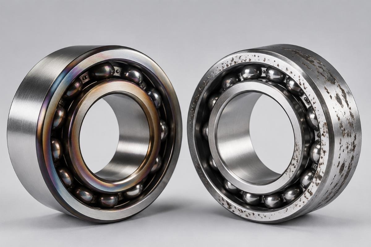
Avoiding these mistakes requires more than knowing the clearance grades — it requires verifying that the bearings you receive actually match the clearance specification you ordered.
How to Source the Correct Clearance Grade with Verified Traceability?
Selecting the right bearing internal clearance is only half the solution — the other half is ensuring the bearings you receive match that specification exactly, with documentation you can verify. In a market where clearance designations can be mislabeled or mixed during distribution, batch-level verification becomes a critical quality control step.
Every bearing we supply carries a batch number that can be cross-referenced against SKF records to confirm the clearance grade, precision class, and manufacturing origin. This traceability is not a certificate that sits in a file — it is a verification tool that procurement and engineering teams can use to confirm they received exactly what was specified, down to the clearance group.
For standard clearance grades in common sizes, stock availability allows rapid dispatch. But the real test of a distributor’s capability comes with rare designations — large bore sizes, special precision classes, non-standard clearance combinations, or ceramic and stainless variants. These specifications often carry factory lead times measured in months, yet production emergencies and project deadlines do not wait. Maintaining deep stock of these rare designations enables dispatch within days rather than weeks, bridging the gap between engineering requirements and supply reality.
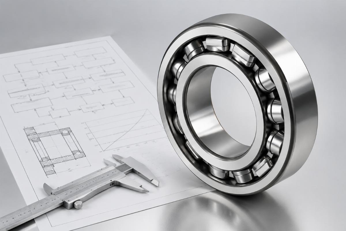
Per-batch precision inspection provides an additional layer of assurance. Before shipment, each batch undergoes dimensional verification to confirm that the internal clearance falls within the specified ISO 5753 range for the designated grade. This inspection catches any manufacturing variation or handling damage that could shift the clearance outside acceptable limits — a step that becomes especially important for C2 and modified clearance specifications where the acceptable range is narrow.
For OEM applications requiring custom clearance specifications — such as the modified C3 developed for the wind energy gearbox mentioned earlier — the combination of technical collaboration, batch traceability, and precision inspection ensures that every unit delivered matches the engineered specification consistently across production runs.
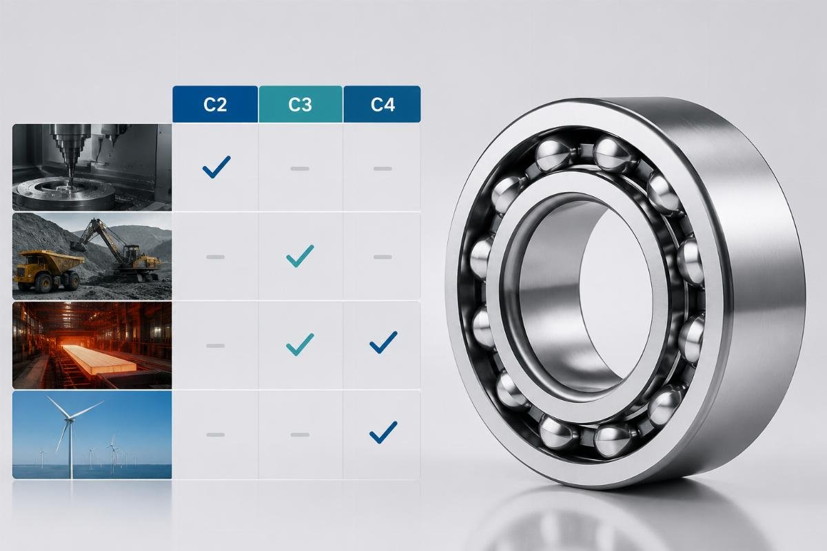
The sourcing decision for bearing internal clearance ultimately comes down to three factors: technical accuracy of the specification, verifiability of the product received, and reliability of supply when non-standard grades are needed. A distributor who can address all three — with documentation, inspection, and stock depth — transforms clearance selection from a source of field failures into a controlled, repeatable process.
Conclusion
Bearing internal clearance selection is an engineering calculation, not a catalogue default. C2, C3, and C4 each serve distinct speed, load, and thermal conditions — and mismatching clearance to application causes the majority of preventable bearing failures in industrial equipment. Calculate effective clearance after thermal expansion and fit interference, verify the specification with batch traceability, and source from a partner who can deliver rare designations with documented precision.
Leave a Reply